Let’s do a little recap from the first half. Last month, I showed the reduction in strength when loading a web tie down strap, a 2 inch lifting sling, a V strap leg and a 3/8” steel core wire rope over a 90 degree corner, and not necessarily a sharp one. The average reduction in strength was 37% when loaded over the outside corner of a piece of 2 inch angle iron.
I also showed what the same towing tools look like when they are cut, as opposed to being overloaded. In this article, I want to show how chain reacts when loaded over a corner, talk about some methods of preventing the same tools from being damaged, and, finally, what to look for when inspecting your straps, wire rope and chain.
I also need to repeat the disclaimer: Please be aware that this testing was done with new product under controlled conditions. NO product should EVER be used above its WORK LOAD LIMIT. Minimum break strengths should NEVER be used to determine the suitability of a product. Failure to follow these warnings may result in property damage, personal injury or death. The intention of this article is to show the effect of improper loading over a corner has on the product.
Time to talk about chain. While chain is arguably the most durable of the tools we are testing, it does have its limitations. When misused or abused, it can fail. Unlike web and wire rope, chain can tell a story. As our National Sales Manager Chip Kauffman has explained before, through testing, it can be shown what the highest load a piece of chain has been loaded to. When chain is made, it is proof tested to twice its Work Load Limit. This stretches the chain very slightly. For a section of 3/8” Grade 7 chain, the Work Load Limit is 6600Lbs, so proof test is 13,200 Lbs. Let’s say this same piece of chain is loaded to 19,000 Lbs, nearly three times its WLL. The chain has already been slightly stretched when it was proofed at 13,200 Lbs, so it will not stretch until the load passes 13,200 Lbs. Once the load exceeds 13,200 Lbs, the chain begins to stretch. This can be seen on the graph when the indicator line changes direction. The same effect happens when the chain is overloaded. It will not stretch until the load exceeds the point at which it was overloaded. Once again, the indicator line on the graph will be nearly vertical until 19,000 Lbs is passed. The chain will begin to stretch, the indicator begins to move horizontally, and the point at which it does is the maximum load the chain has seen. To illustrate this, I loaded a piece of 3/8” G7 chain to 18,400 Lbs. Proof test on this pieces was 15,100 Lbs. The same piece of chain was pulled to destruction. The previous load of 18,400 Lbs is visible on the graph.

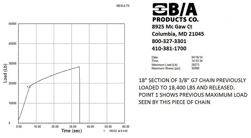
Graph on left shows 18” section of 3/8” G7 chain loaded to 18,400 Lbs. Mark 1 is proof test load of this chain, 15,100 Lbs. Graph on right shows same section of chain loaded to destruction. Mark 1 shows previous maximum load of 18,400 Lbs. Chain has a memory.
In addition, chain has what is known in the industry as a preferential failure. Chain is designed to be pulled in a straight line, end of one link against the end of the adjacent link. When a chain is loaded in other than a straight line, such as when a grab hook is hooked over a link to form a loop, the chain will fail at that point, and by as much as 20% below the minimum.
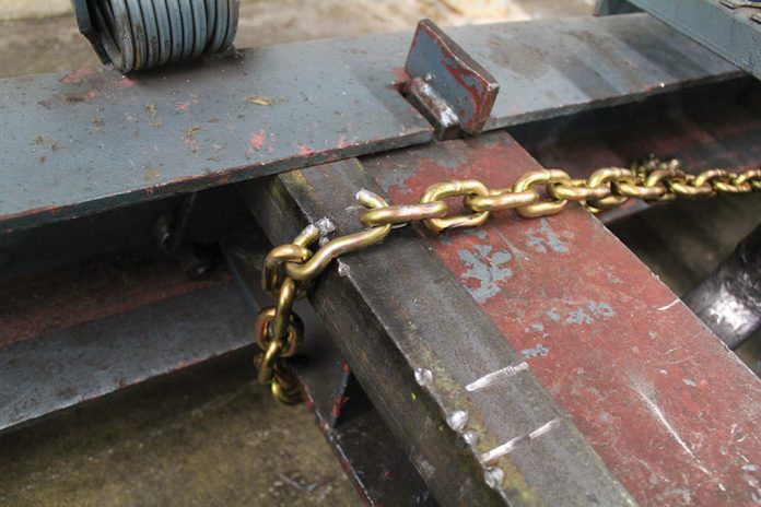
Enough talk, let’s do some testing. I set up the test bed the same way as I did for the previous tests, with a piece of 2” x 2” x 3/16” angle iron. I then attempted to load the chain so the link was pulled over the angle. For these tests, I used 5/16” grade 70 chain with a Work Load Limit of 4700 Lbs, and a minimum break of 18,800 Lbs. I pulled one chain to use as a control sample; it failed 19,875 Lb, a shear at the end of the link.
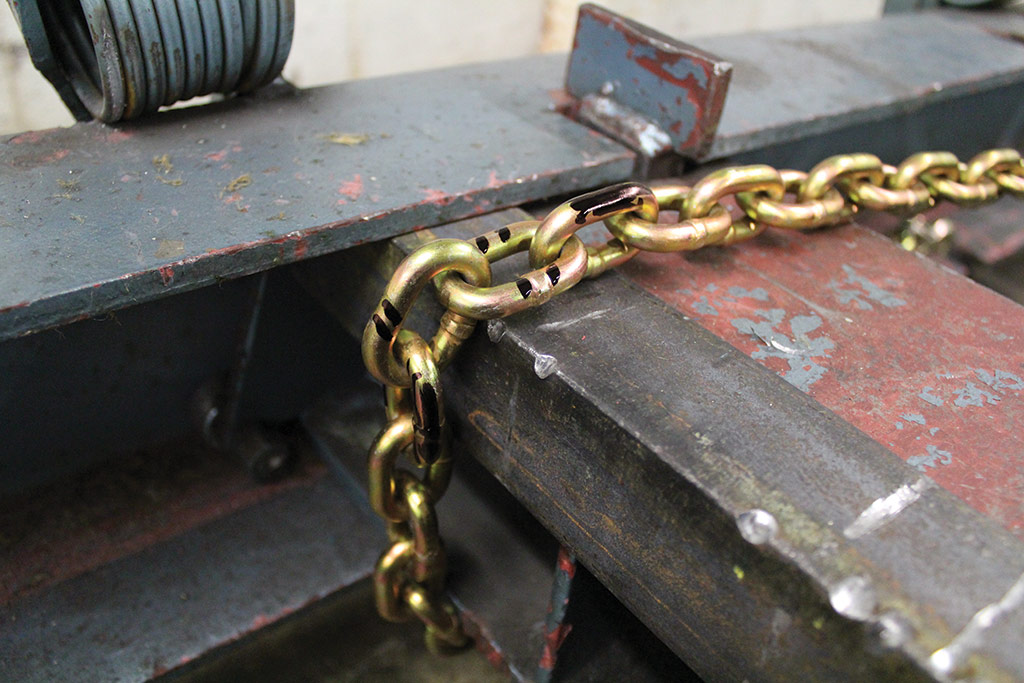
The photo shows the test set up. The links were marked showing which were in contact with the corner of the angle.
The 3 samples tested over the angle failed at 15,055 Lbs, 12,803 Lbs and 15,574 Lbs, for an average of 14,477 Lbs, an average 28% reduction in breaking strength. If you look at the links that failed, a pattern emerges.


All of the links failed in the middle of the link, unlike the control that sheared on the end. All three also failed where the link was in contact with the angle. While it appears to be a weld failure, the failure occurred adjacent to the weld. There are also contact marks from the adjacent links and the angle. In addition, there is no “necking down,” a reduction of the links diameter commonly seen in straight pull tests. Due to the load being concentrated on one side of the link, and the mechanical damage caused by bending the link over the angle, the chain failed below minimum.
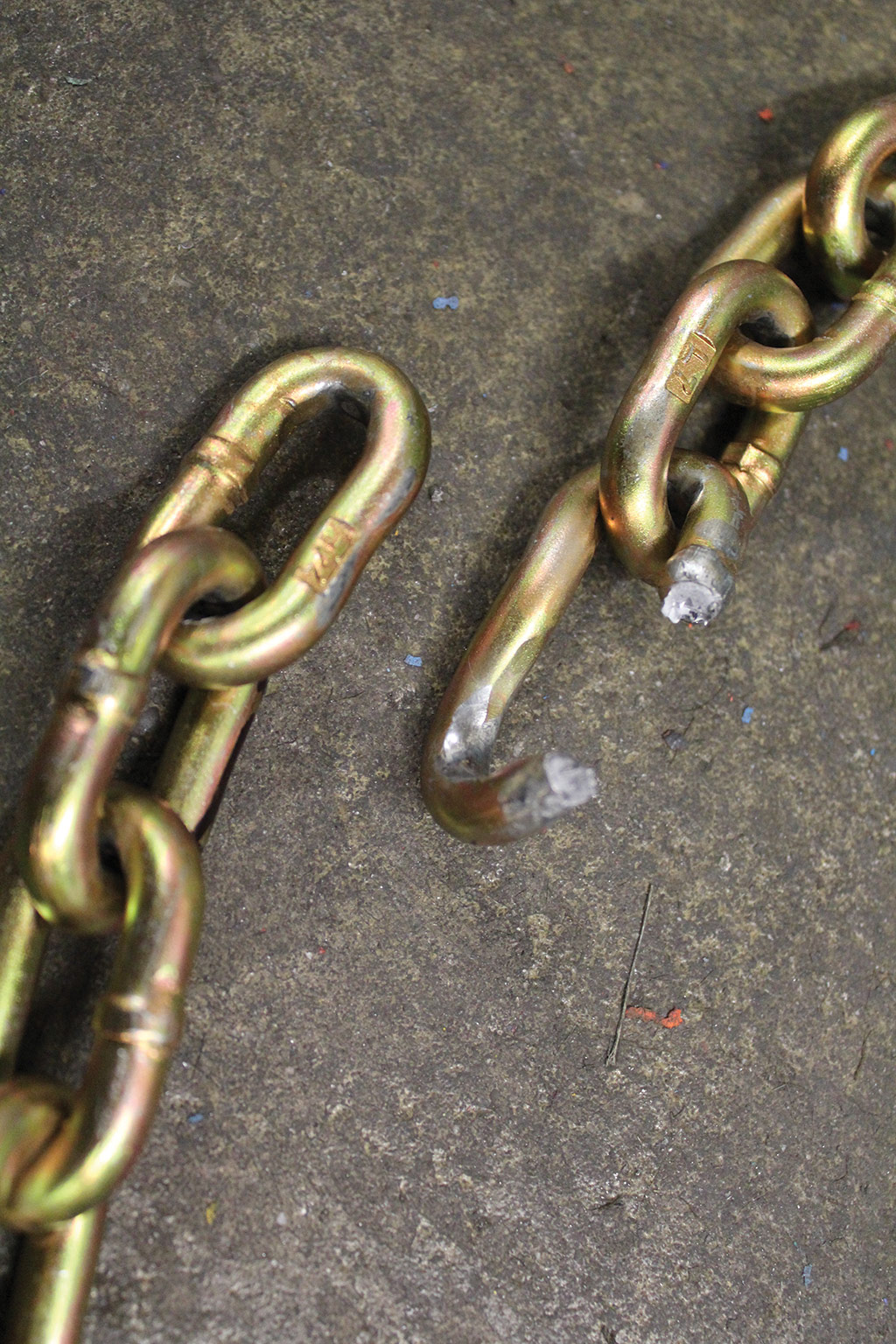
A close up of one of the links, showing the weld intact.
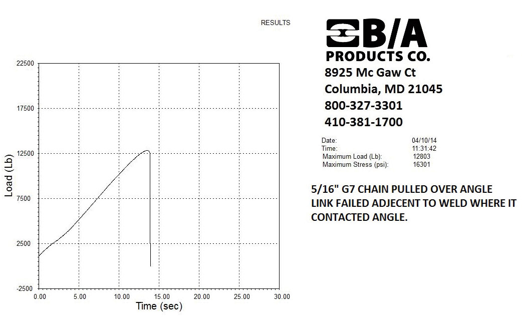
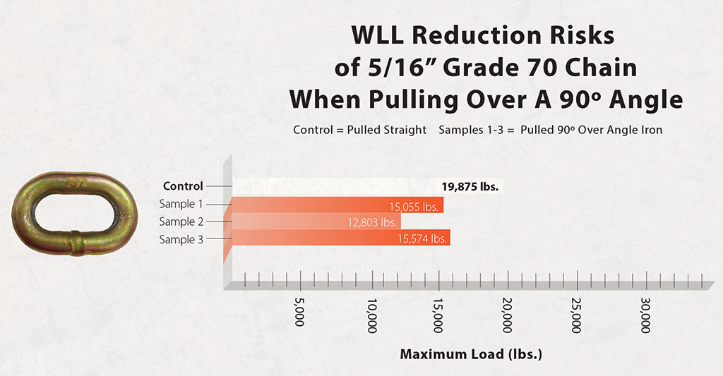
Top: Graph of the above link. Bottom: Graph showing reduction of break strength of 5/16 G7 chainover angle
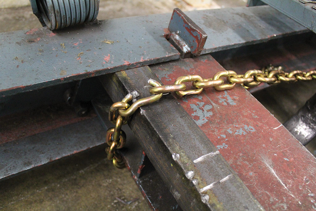
Every now and then, I get lucky. Usually when a failure occurs, the parts go flying. In this example, a quick hand on the switch stopped the tester at point of failure, and the parts remained in place. While the load was being applied, only one leg of the link was in contact with the angle. At failure, the link rotated 90 degrees towards the camera and came to rest as you see here.
So once again, I have shown that loading over a corner can reduce the ultimate breaking strength. How do we prevent this from happening? There are some general things that can be done that apply to all the tools I have tested, and some specific things for each product.
General Precautions:
First thing is to NEVER exceed the products Work Load Limit. In all of the tests I did, the samples failed above the WLL, and in 3 out of 4, at twice the WLL. This is not to say that corners or sharp objects will not damage these tools if the WLL is not exceeded, but it will help reduce damage, and is good practice.
Watch how the strap, chain, or wire rope is routed, and avoid contact with anything they may cause wear or damage. This includes the load or cargo that is being secured or moved.
Regularly inspect and maintain your straps, wire rope and chain. I’ll go into specifics for each product, but regular inspection can prevent a small problem from becoming a large one.
Make sure your tie down or tie downs have sufficient Work Load to restrain the object being moved. If not, add tie downs until they do. In addition, make sure the tie down points you are hooking to are rated for the tie down. A strap and ratchet with a 3300 Lb WLL hooked to a D ring with a 1000 Lb WLL is only good for 1000 Lbs!
NEVER shock load any of the tie downs we are discussing.
Product specific precautions:
Web slings and tie downs:
Of all the items I tested, web is the most easily damaged. Any place that web contacts the cargo, the load being moved or the tow vehicle itself must be protected or moved. I have shown that tensioning a load over a corner, even on as seemingly innocent as the corner of a piece of angle iron, can damage the web. A hand ratchet can tension a piece of tie down web to about 1400 Lbs, well below the WLL of most tie downs. If the strap is tensioned over an edge, the vibration on the vehicle going down the road can and will wear and possibly cut the strap. In addition, when hauling a vehicle, the can be some movement, which will also accelerate wear. This can also happen with V straps. If they are under tension and in contact with the under frame or suspension, the vibration and movement will wear the web.
I did a quick test to show the effectiveness of three different sling pads on a tie down strap. I tested one sample each of a cordura sleeve, a cordura pad sewn to the strap and a rubber pad. I’ll let the results speak for themselves:
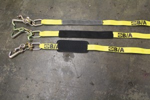
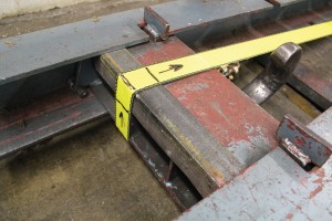
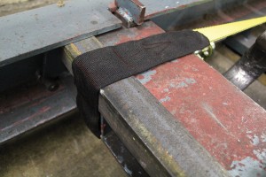
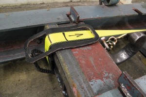
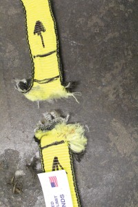
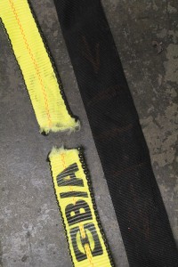
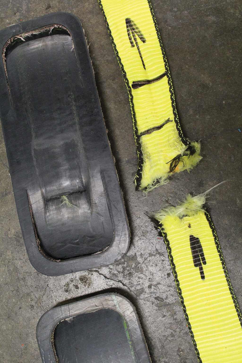
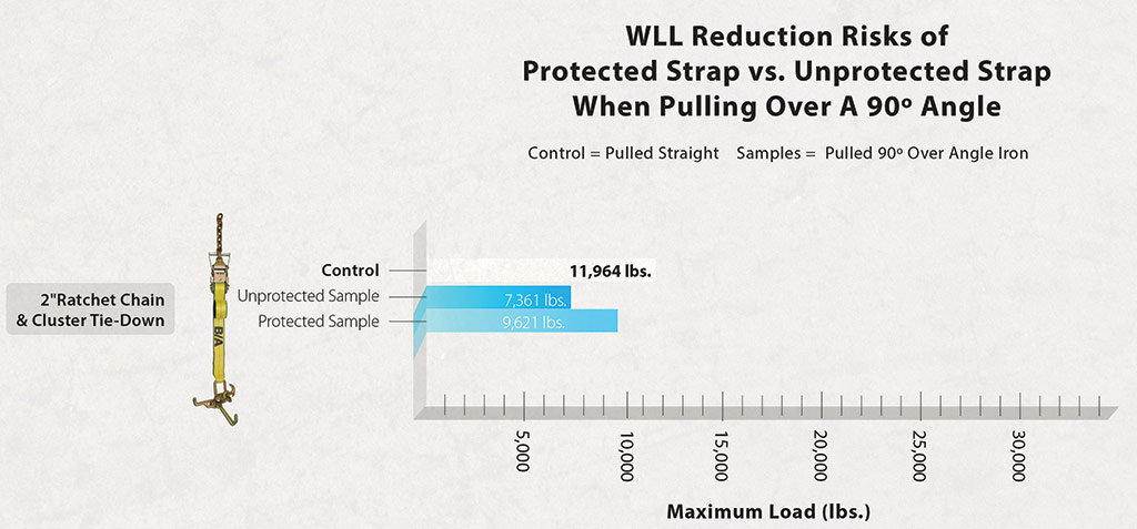
Top: rubber pad failed at 11,319 Lbs Bottom: graph showing average increase in break strength padding provides
While the strap still failed where it contacted the angle, the average failure was 9621 Lbs, a 30% increase over the unprotected strap. While further testing is required to validate the results, I think I can predict that the protected strap will break at a higher load.
Wire Rope:
Wire rope is the second most easily damaged. Improper drum winding, which can lead to crushing and flat spotting, will quickly turn a new wire rope into a useless piece of scrap metal. This is commonly seen on roll backs. Once the wire rope crosses over itself and a load is applied, the layer underneath is irreparably damaged.
Wire rope also has a minimum bend radius. Whether the wire rope is being bent around a sheave or another object, wear, fatigue and reduction in strength is occurring. The smaller the radius the wire rope is bent around, the greater the wear and the greater the reduction in strength. This is commonly referred to a D/d ratio, where D is the diameter of the sheave or other object the wire rope is wrapped around, and d is the diameter of the wire rope. The higher the ratio, the lower the wear, fatigue and reduction in strength, and the lower the ration the higher the wear, fatigue and reduction in strength. For example, a 3/8” wire rope being pulled around an 8” sheave has a D/d ratio of 21.3, and this rope would have about 92% of its breaking strength. The following graph shows the effect the D/d ratio has on the strength of the wire rope.

Graph shows the effect of D/d ration on ultimate strength of wire rope
It is also vitally important that when wire rope is used over sheaves, such as in a snatch block or at the end of a wrecker boom, that the sheave grooves be correctly sized for the wire rope being used. Sheave grooves that are too small can pinch the rope and prevent the individual wires and strands from adjusting (necessary movement within the rope itself; grooves that are too large will not support the rope, allowing it to flatten and restrict free movement. When a change in direction is required in a run of wire rope, it should always be routed over a sheave or roller. Pulling a wire rope over an edge (such as the end of a roll back bed) will damage the rope. Yes, I have seen this done. Finally, lubrication of wire rope can increase its life. There are several lubrication products specifically for wire rope.
Chain: While chain is the most durable of the products I tested, it still requires care in its use. Chain is designed to be used in a straight line, tensioned end of link to end of link. Avoid wrapping chain over itself. Only use hooks and fittings that are sized properly for the chain (1/2” hooks on ½” chain for example). Chain should not be twisted, knotted or kinked. Avoid temperatures above 400 degrees F for grade 70, 80 and 100.
Inspection
Most inspection criteria I have seen calls for three types of inspection: Initial, Frequent and Periodic. Let’s look at each quickly:
Initial: Before any new product is put into use, it should be inspected by a designed person to verify it is correct of the application and in undamaged condition.
Frequent: Before each use, the person using the product should inspect it.
Periodic: This inspection should be conducted by a designated person. Frequency of this inspection should be based on frequency of the products use, severity of service, and experience gained in the service life of similar products.
While we can debate the need and frequency of inspections, I hope we all can agree that they are necessary. But what are you looking for? And who is this designated person? I did a little searching and came up with the following: “Designated” personnel means employees selected or assigned by the employer or the employer’s representative as being qualified to perform specific duties. The designated person should have some background or training that makes him knowledgeable about the items he is inspecting.
So what is this designated person looking for? I am going to cover out of service criteria for each group of product that was tested.
WEB SLINGS AND TIE DOWNS: A web sling or tie down shall be immediately removed from service and destroyed if any of the following are observed:
If the capacity or material identification tag is unreadable or missing
If any acid or alkalis burns are present
If any melting, charring or weld spatters are present
If any holes, cuts, snags or embedded particles are present
If there are any broken or worn stitches in the load bearing splice
If there is excessive abrasive wear
If there are knots in any part of the sling or tie down
If there is excessive pitting or corrosion, cracked, distorted or broken fittings
If there is any other visible damage that causes doubt to the strength of the sling
(Photos of these conditions can be found on our web site: www.baprod.com)
WIRE ROPE: A wire rope winch line or sling shall be removed from service immediately and destroyed if any of the following are observed:
Kinks, bird caging or popped core in the working section of the wire rope
Discoloration due to excessive heat
Corrosion with pitting of the wires
More than 11 broken wires in six diameters of length
More than three broken wires in any one strand
More than two broken wires at the end connection
CHAIN: A chain shall be removed from service immediately and destroyed if any of the following are observed:
Any links or components are worn, bent, gouged or stretched
Any links or components are cracked or distorted
Any link measures below the NACM standard thickness as shown in chart XIV found at http://www.nacm.info/welded.php
I hope you have found this article interesting and informative. It is not intended to be the be all end all discussion; rather, my goal was to make you aware of some of the common signs of misuse and abuse that can reduce the strength and useful life of web, wire rope and chain products. Cutting corners can be dangerous. I encourage you to use the following links to gain more knowledge:
B/A Products www.baprod.com
National Association of Chain Manufacturers www.nacm.org
Web Sling Tie Down Association www.wstda.com
Associated Wire Rope Manufacturers www.awrf.org
Wire Rope Technical Board www.thewireropethenicalboard.org

